3D Modeling with a UAV
There are multiple ways in which a three-dimensional model (3D) of a structure or terrain can be constructed. These include, using multiple cameras on airplane, LiDAR (to be discussed in another section) and overlapping images of the same feature flown with an Unmanned Aerial Vehicle (UAV) or Drone. In this lesson the focus will be on the overlapping images from a UAV.
The concept is the observation of an object from different locations (angles) and then combining the images together to create a 3D model. A simple example would be, if you cover one of your eyes and look at an object it lacks depth. If you then cover the other eye, the object will appear to have shifted position. These slightly different viewing angles (the separation of your eyes) allows the human brain to give depth to an object when being observed, since each eye is seeing the object slightly different. A camera on a UAV captures images along a flight path. The camera is programmed to take overlapping images, both front to back and side to side. Software generates the location that each image was taken by using the on board GNSS system. The height of the vehicle, the focal length of the lens on the camera and the size and number of pixels of the CCD chip are other variables that influence the image construction and resolution.
Each image can be considered a two dimensional point cloud, every location should appear in a minimum of two images but may appear in multiple images. By tying common points together a structural elevation and volume can be determined. This is done by including the location of the vehicle when each image was taken through the use of the GNSS measurements. These processes are done with software because the number of points in the point cloud requires millions of calculations. Depending on the quality of the imagery and the application utilized, multiple parameters can be determined.
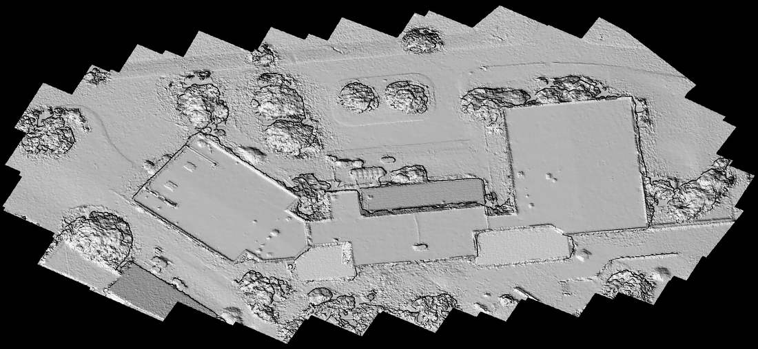
Figure 1: Hillshade of the Library, Administration building (GeoTech Center) and the Auditorium of the Southwest Campus of Jefferson Community and Technical College. Created using Drone Mapper, from UAV imagery, pilot Chris Wright.
Drone Mapper RAPID
Dronemapper RAPID is a Windows based application used to analyze image data gathered by UAVs. It can be used to produce Orthomoasic images and scaled DEMs (Digital Elevation Model). The free version of this software can be downloaded here. Install the software on a local hard drive of your computer.
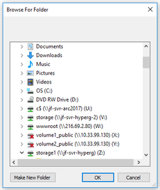
Open the Drone Mapper RAPID application, choose File tab and ‘Open JPGs’. Browse to the folder containing the unzipped (decompressed) image data, select the folder and then choose Ok.
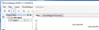
The images will be loaded into the application.
Select the ‘DroneMapper Processing’ tab.
Select the ‘DroneMapper Processing’ tab.
Check the ‘Overnight Mode’ box, and High Features, then choose OK and press the Play button.
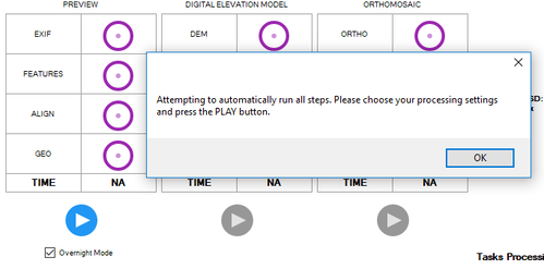
All of the processes for the image data will run. This may take a fair length of time depending on the speed of the computer being used.
After processing select the ‘Map’ tab to examine the different layers. These layers have been stored in the same folder as the original data.
After processing select the ‘Map’ tab to examine the different layers. These layers have been stored in the same folder as the original data.
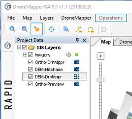
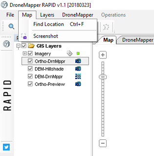
Images of the different layers can be saved using the 'Screenshot' tool.
Example of Screenshot, note the green dots are the location of the UAV when each image was captured.
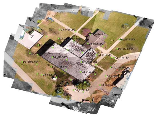
Figure 2: Orthomosaic of the Social Science Building on the Southwest Campus of Jefferson Community and Technical College, pilot and creator Chris Wright.
|
Once Dronemapper application has completed the operation, new files should have been created that can be loaded into a geospatial application. Therefore, it is important to know the storage location of the data that was created in the application. Make sure the Dronemapper is closed prior to attempting to load the data in the geospatial application program. Once the files are loaded into the geospatial application include a basemap, which should show that geospatial data is well aligned to the earth's grid. Use different color ramps change the appearance of the Hillshade and DEM. A color change cannot be done on the ortho image (the stitched image) because it is a picture.
For those wishing to extend their knowledge it is recommended that the user, load the images into ArcGIS Pro, because this 64 bit architecture does image processing much better than 32 bit applications (see the discussion on GIS mosaic image construction for more information on how to use this application). Load the DEM file into ArcGIS Pro, load a basemap and then select the Imagery tab. Click on the Raster Function button, which should open a new Window (generally appears on the right side of the screen), at the bottom of this Window select Surfaces and then the Shaded Relief icon. Use the DEM file as the input file and then use the defaults. Repeat the process by changing different parameters including the ramp colors. |
