Geospatial Image Mosaic
This lesson will utilize geospatial software to create a mosaic image that can be used for analysis. There are many different software packages that can be used some are made specifically for UAV images and other are more generic geospatial software. For this lesson the Esri ArcGIS Pro software (application) will be utilized. To download the software by selecting the button. ArcGIS Pro authorizes via the Internet.
The ArcGIS Pro application must be installed, the users will need to use their Esri account to login into the software after it is installed. Make sure the account has been placed into the organization account, if unsure contact your instructor. The application may prompt for updates. This application is a 64 bit program and must be installed on a 64 bit computer system.
Process
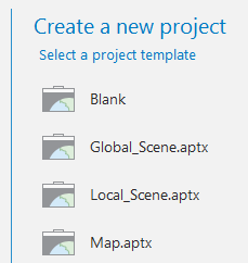
Open the ArcGis application; under ‘Create a new project’ choose ‘Blank’. Give the project a name.
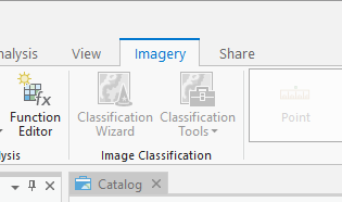
Next, choose the ‘Imagery’ tab.
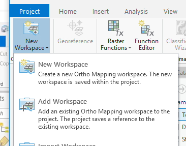
Then select ‘New Workspace’.
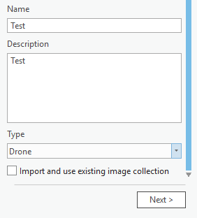
On the right hand of the screen, give the project a name and a description, for ‘Type’ choose 'Drone’. Choose ‘Next’ to move forward.
Use the ‘Add’ Button to insert image data into the project. Choose the image data at the folder level.
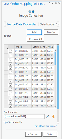
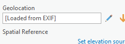
Next click on the pencil symbol under ‘Geolocation’.
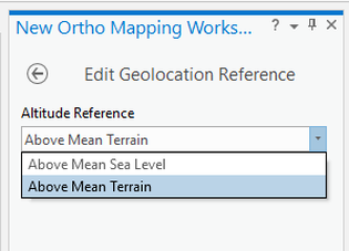
Change the setting to ‘Above Mean Terrain’ and hit OK. The rest of the settings will stay in the defaults. Choose Finish and the images will be processed.
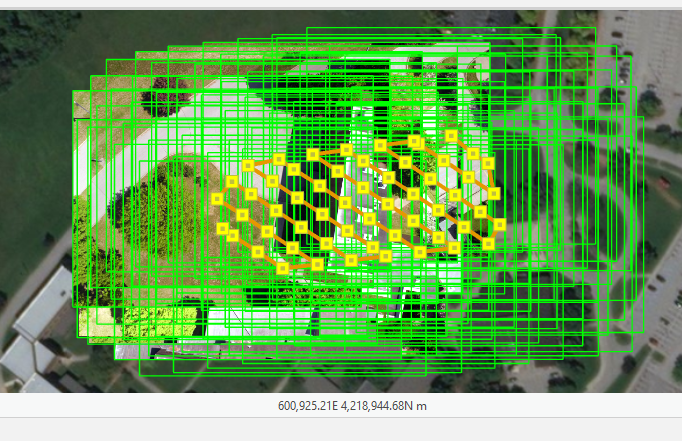
The processed image should look like the screenshot below.
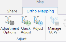
Next, choose the ‘Adjust’ button to arrange the images. This process will take time (20 minuets or longer) depending on the power of the computer being used.
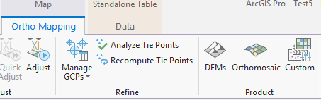
Under the Ortho Mapping tab, choose ‘Orthomosaic’. The Orthomosaic Wizard will appear on the right side of the screen.

Hit the ‘Next’ button at the bottom right of the screen, leaving all the default settings in place. Finally hit the ‘Finish’ button to create the Orthomosaic image.
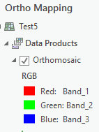
The Orthomosaic can be turned on and off in the table of contents.
Next, from the Ortho Mapping tab choose the ‘DEMS’ button, this will bring up the DEMS wizard on the right hand of the screen. Choose the defaults as in the Orthomosaic wizard.
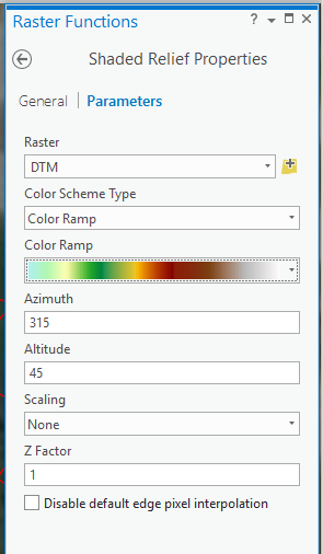
Choose the Analysis tab, then select Raster Functions tab towards the right side of the tab bar.
The Raster Functions tab will appear on the right hand side of the screen. Under the ‘Surface’ section, choose ‘Shaded Relief’.
The Raster Functions tab will appear on the right hand side of the screen. Under the ‘Surface’ section, choose ‘Shaded Relief’.
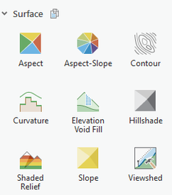
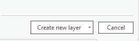
Under the raster pull-down choose ‘DTM’, choose a color ramp, and then hit ‘Create New Layer’.
|
|
